I’ve recently completed an Honours Degree in Software Development and as part of this I spent a few months off and on working on a proof of concept tracking system utilising Bluetooth Low Energy (BLE) in order to track small asset tags. I believe this system could quite easily be scaled up to an industrial scale with further work but don’t personally plan to follow this up in the near future due to working on other projects. As such I figured I’d release a lot of what I have and hopefully it can help somebody else.
If you do something cool with this then please get in touch, otherwise do with it all as you wish.
This post is one of eight scheduled to be released over the next few weeks, all posts in this series may be found by selecting the tag below.
This post functions as a log of the steps required to implement this project in a practical manner, the goal is that somebody else with minimal knowledge may be able to follow it.
Programming the NRF51822 BLE Tag
The BLE beacon will transmit every 30 seconds and will also push through data regarding whether the button has been short or long pressed, this could potentially be used to automatically deprecate or change the status of an asset to reduce overhead time.
Instructions are similar to previous stage, but the connectors are slightly different.
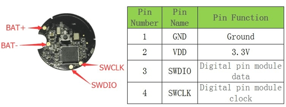
| NRF51822 | Raspberry PI 4 |
| SCLK/SWCLK (Input) | GPIO 25 Pin 22 |
| SDD/SWDIO (Output) | GPIO 24 Pin 18 |
| BAT + | 3V3 Power Pin 1 |
| BAT – | GND Pin 6 |
The code for this has already been developed by Eric Tsai and can be found here – https://os.mbed.com/users/electronichamsters/code/BLE_Sensor_Button/
This must be compiled and flashed to the device as per the previous post.
Programming the ESP8266 Wi-Fi Chip
The ESP8266 can be programmed from the Arduino IDE which makes it straightforward to program luckily. It will be connected to the BLE module and will receive BLE data, process it to MQTT then publish it to the local Wi-Fi network.
Download and Setup Arduino IDE
First step is to download the Arduino IDE which will let us program the ESP8266 chip, this can be done from https://www.arduino.cc/en/Main/Software
Once installed open it up and then we need to add support for the ESP8266 –
- Go to File > Preferences.
- Add the following to ‘Additional Board Manager URLs’ –
- Close then re-open the Arduino IDE.
- Go to Tools > Board > Board Manager.
- Search for ESP8266
- Install the board manager.
Programming the ESP8266
Before attempting to connect to the device, first we need to verify that it is properly connected.
- Connect the ESP8266 module to the Raspberry PI using a microUSB to USB connector.
- In the Raspberry console type ‘lsusb’ to view connected devices.
- There should be a device called “CP2102/CP2109”, if not try a different cable.
- Then type ‘dmesg | grep “tty” to return all connected devices and their serial port, for USB this is likely to be ttyUSB0.
Note: The Raspberry Pi cannot power both the ESP8266 and the NRF51822 modules in serial. They must be disconnected to program the ESP8266
Using the Arduino IDE, do the following before programming –
- Go to Tools > Board > ESP8266 Boards > Generic ESP8266 Module.
- Go to Tools > Port
- Select the port that the device is attached to. (/dev/ttyS0 for USB)
- Open or write a script.
- Click Compile to start compiling the sketch to the device.
- The script will run as soon as it is uploaded.
- Output can be found using the Serial Monitor
The specific code we need to run on the ESP8266 module will be this – https://github.com/ShaunWilkinson/NRF5188_BLE_to_MQTT/blob/main/BLE_MQTT_Bridge.ino
Debugging
Arduino IDE comes with a Serial Monitor which we can use to monitor any serial output from the chip.
- Open Arduino IDE.
- Ensure the correct board and port are selected.
- Go to Tools > Serial Monitor
- Change the baud rate to 115200.
Connecting the NRF51822 to the ESP8266
To connect the two devices requires custom Dupont cables for simplicity, although they could also be soldered.
Cables should be connected as below –
| NRF51822 | ESP8266 |
| GND (Ground) | GRD |
| VDD (Power) | 3V3 (3.3V) |
| TX P01.09 (Serial Output) | SD3 |


Leave a comment